FREE KIT INSTRUCTIONS
Building the low
relief Grain Silo
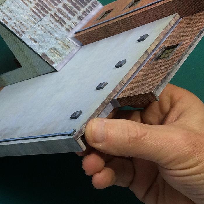
Hornby Magazine and Scalescenes present a brand new 4mm scale kit for ‘OO’ gauge layouts which models a low relief grain silo. JOHN WIFFEN explains how to build this brick and concrete structure using the free kit print included with this issue.
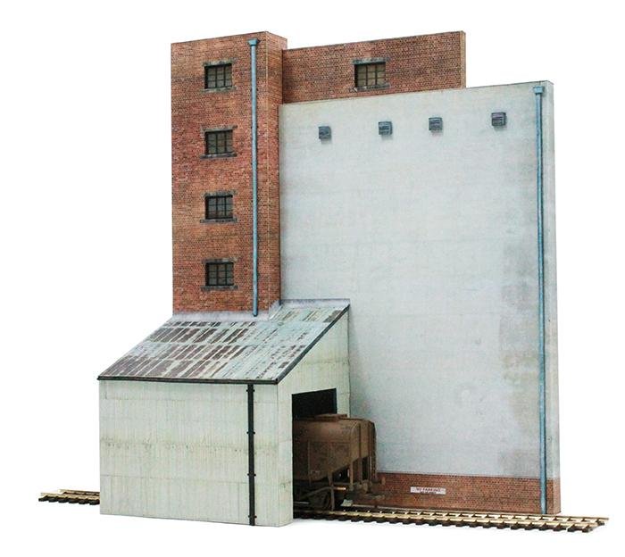
Above: Supplied with this issue is the low relief grain silo building. Visit www.scalescenes. com to see the full range of downloadable home-print kits.
GRAIN SILOS make for impressive buildings. Their austere construction style and the use of simple materials such as brick concrete and metal cladding make buildings like this all the more attractive and a perfect industrial backdrop for a model railway.
The latest kit to be offered free through Hornby Magazine from Scalescenes.com is this ‘OO’ gauge grain silo – the ideal home for Bachmann’s highly detailed model of the BR operated grain hoppers. It has been designed exclusively for this issue by Scalescenes’ John Wiffen to launch it into the market.
Within this issue you will find an A2 sheet containing all the parts needed to assemble the building with the exception of different weights of card required to create the structure.
To enhance your building further, printable transparency windows to fit this kit are available to download from www. scalescenes.com. They are designed to be printed or copied on to transparency or OHP film, available from most office suppliers (both laser and inkjet friendly generic brands are usually fine). Alternative window options include compatible Scaleglaze white screenprinted windows from www. scalescenes.com/scaleglaze (Scaleglaze 13 pack required).
The following step by step guide explains how to build the Scalescenes Grain Silo kit from start to finish.
OPTIONAL WEATHERING
Using a sharp knife scrape a small amount of black and brown artist pastels on to a scrap of card. With a soft brush work very small amounts of the pastel dust into the corners and surface of the structure as required. Build up thin layers slowly, don’t overdo it!
| Tools |
|---|
| Steel ruler |
| Modelling knife |
| Tweezers |
| Glue stick |
| All-purpose clear or PVA adhesive |
| CA or super glue |
| Matt spray varnish |
| Felt tip pens |
| Cutting mat |
| Damp cloth |
| Fine sandpaper |
| Small right-angled square or block |
STEP BY STEP: BUILDING SCALESCENES’ GRAIN SILO
1
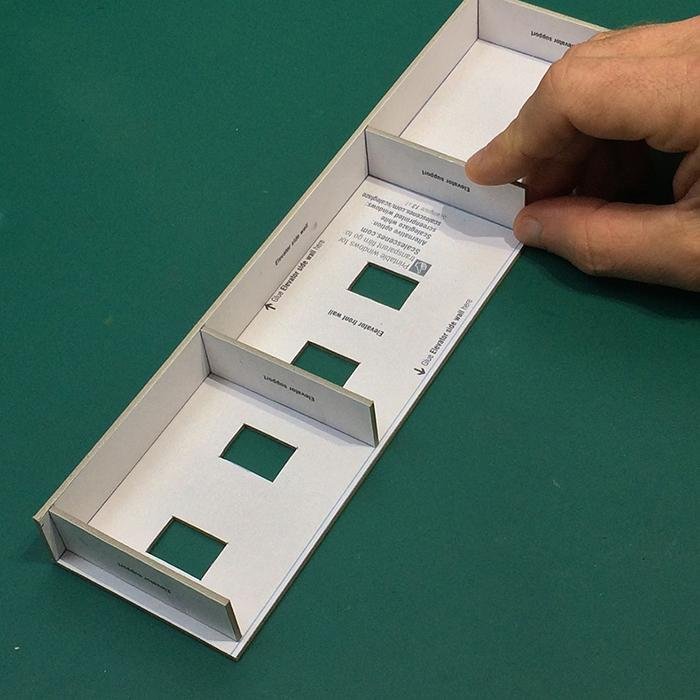
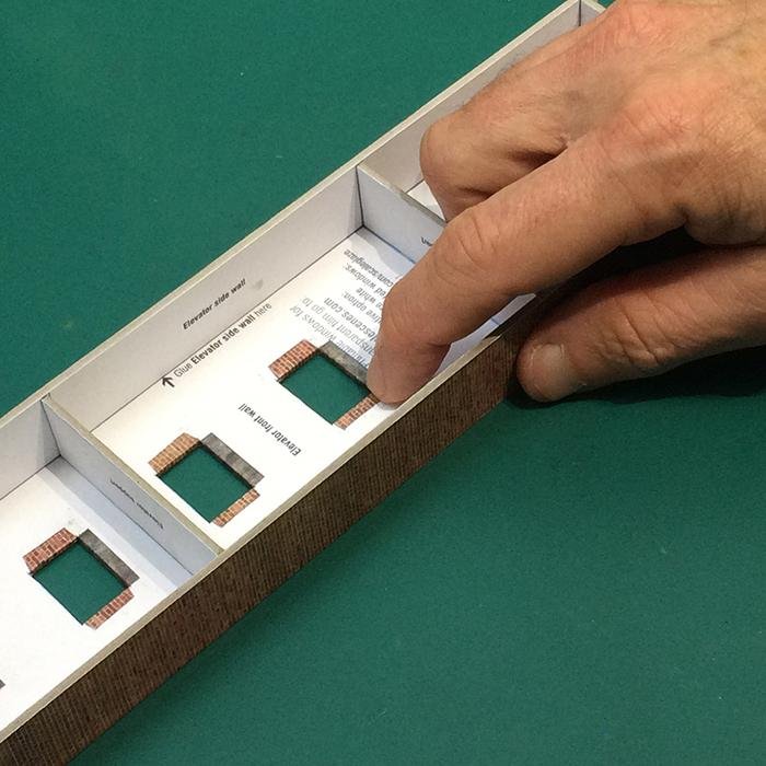
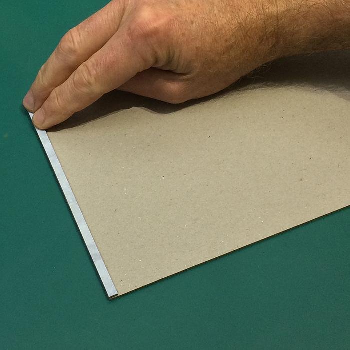
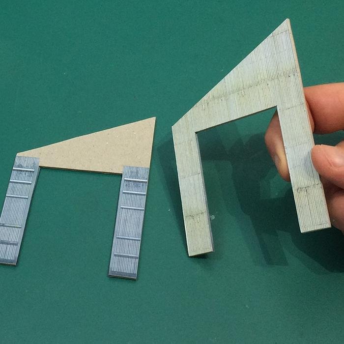
Glue the sheets to Heavy (2mm) or Medium (1mm) weight card as labelled. Using the light blue guidelines, glue one of the Elevator side walls and the four Elevator supports squarely into position.
2
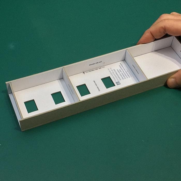
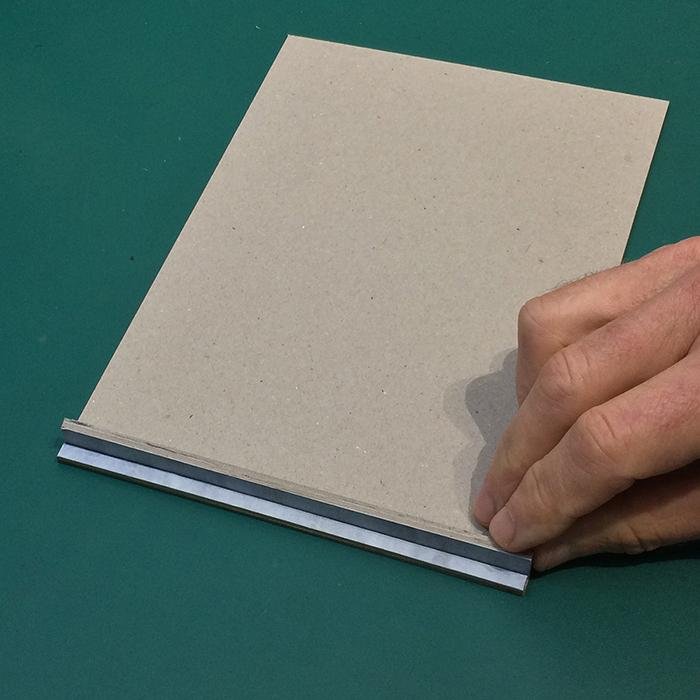
Glue the remaining Elevator side wall into position. Use a small square or block to check that all the walls and supports are perpendicular.
3
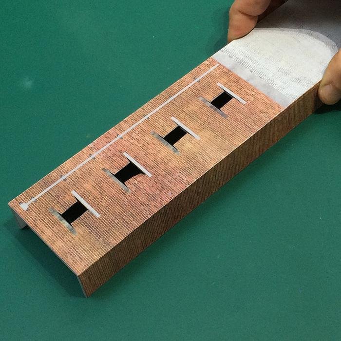
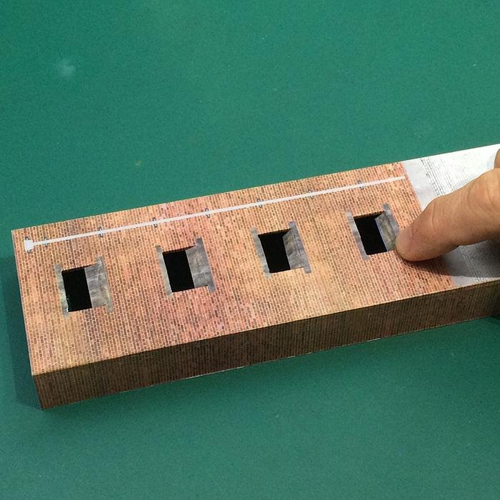
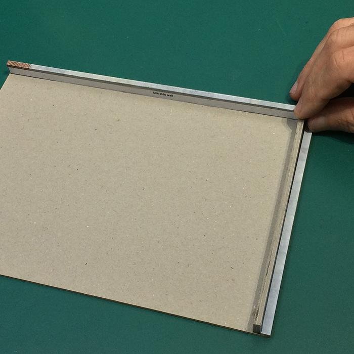
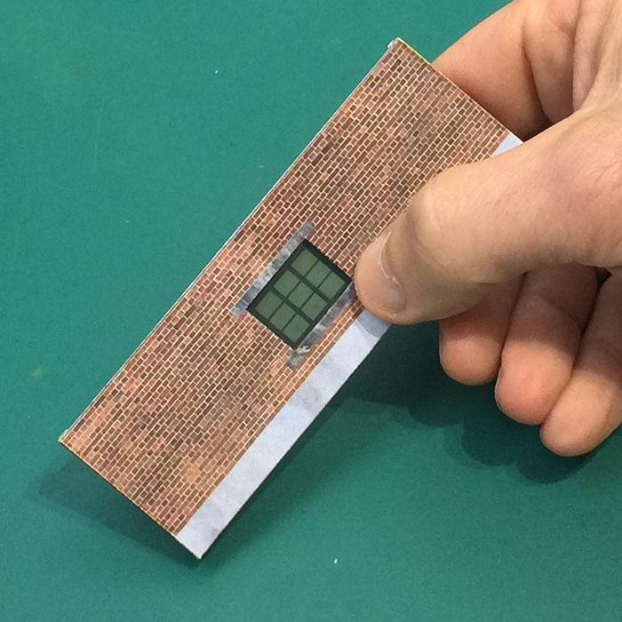
Carefully wrap and glue the Elevator wall cover layer over the base layer structure. Check for bubbles and creases.
4
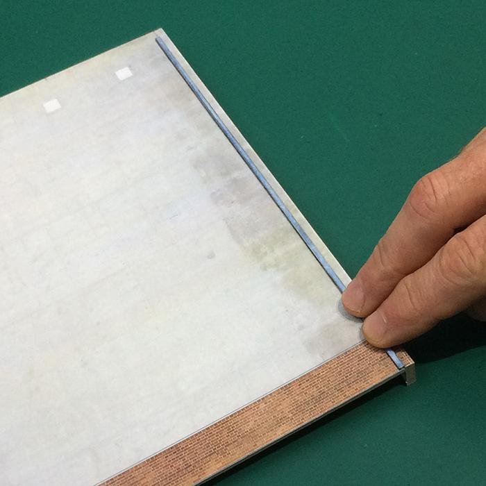
Flip the wall over (print down) and apply a thin bead of glue along the window flaps and gently fold them tightly around the openings.
5
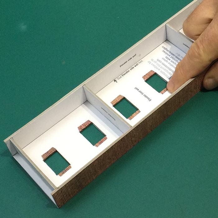
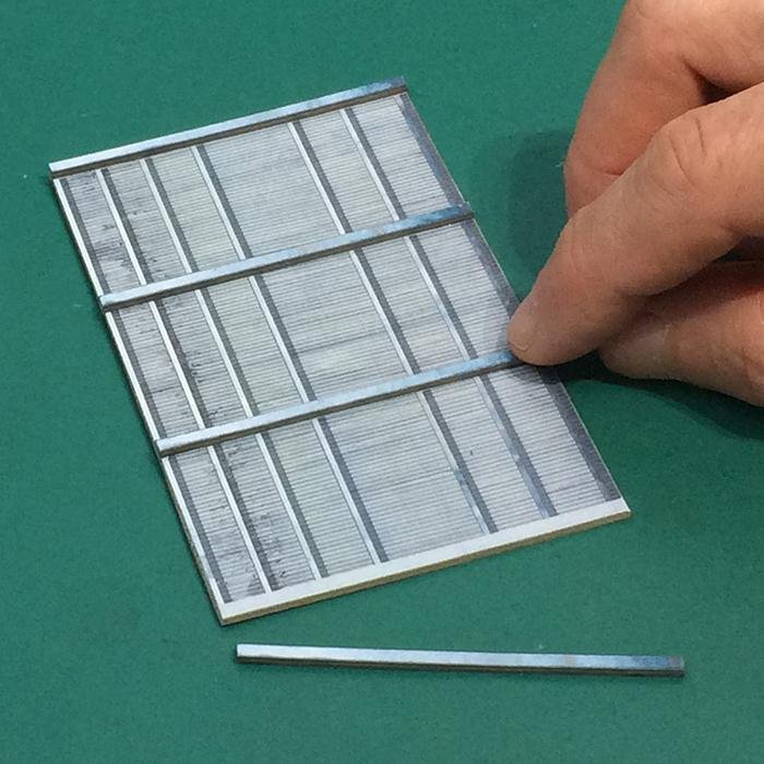
Glue the Elevator sills into position using the cover layers from the printed sheet.
6
Flip the wall over (print down) and apply a thin bead of glue along the sill flaps and gently fold the flaps tightly around the card.
7
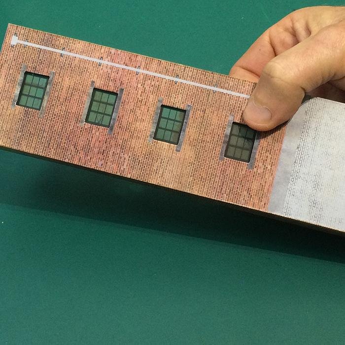
Apply a thin bead of glue around the window openings and squarely position the Windows (download from Scalescenes. com). Turn the wall over and check that the windows are sitting squarely within the openings.
8
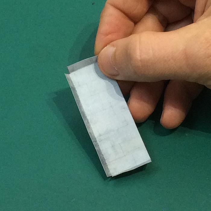
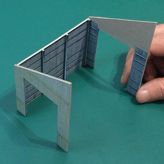
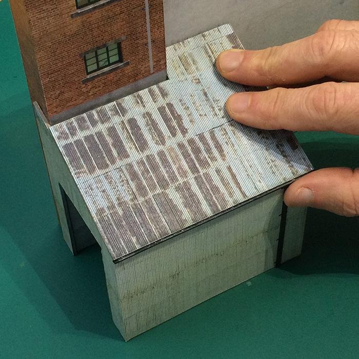
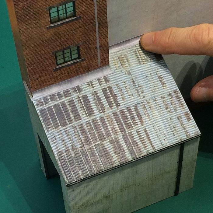
Squarely fold up the edges of the Elevator roof cover layer with the sides above the base section.
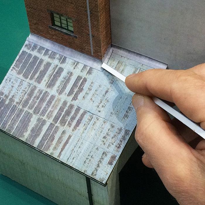
9
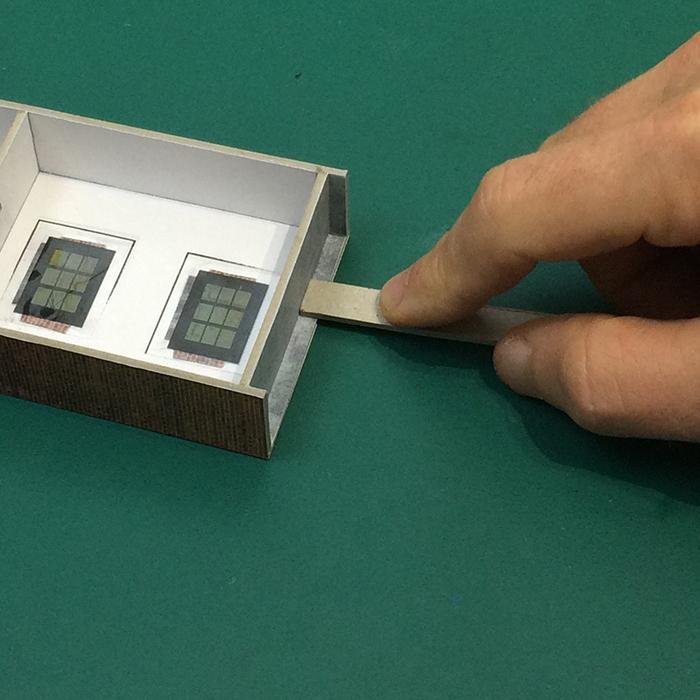
Test fit and glue into position. Use a small strip of scrap card to work the edges into the corners.
10
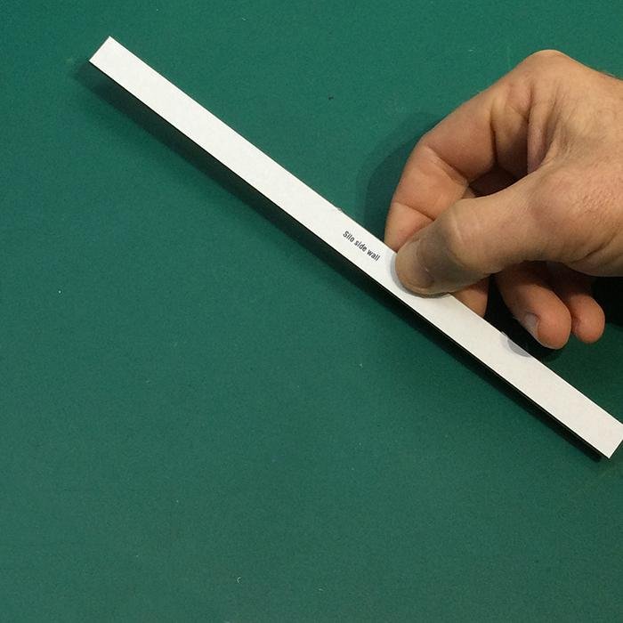
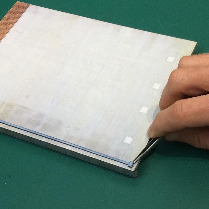
Squarely glue the two Silo side wall base layers together. Apply weight or clamp to ensure good adhesion.
11
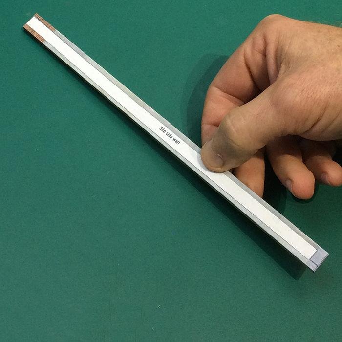
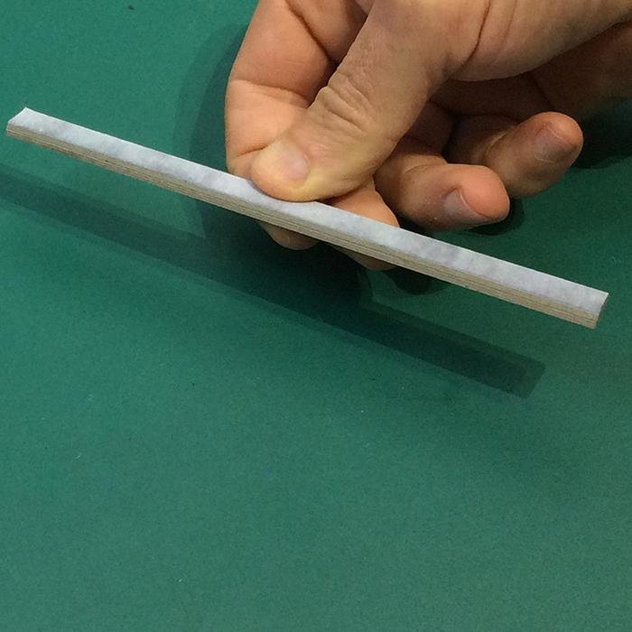
Fold along the blue dotted lines on the Silo cover layers and glue the base layers into the centre. Tightly wrap and glue the side flaps around each edge.
12
Squarely glue the two Silo roof sections together. Apply weight or clamp to ensure good adhesion.
13
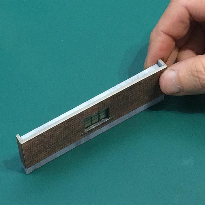
Noting the top of the Silo front wall, place the wall print side down. Squarely glue the Silo parapet along the top edge.
14
Test fit and glue the Silo roof squarely into position on the rear of the Silo front wall.
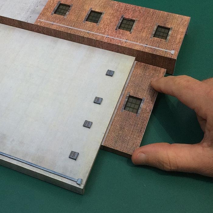
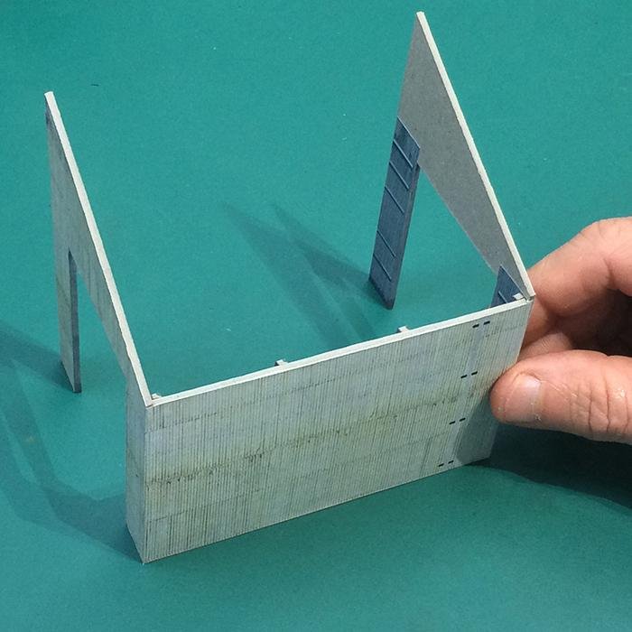
15
Having decided which side of the Elevator the Silo will sit, test fit and glue the Silo side wall squarely along the opposite edge. Use a small square or block to check that all the walls are perpendicular to one another.
16
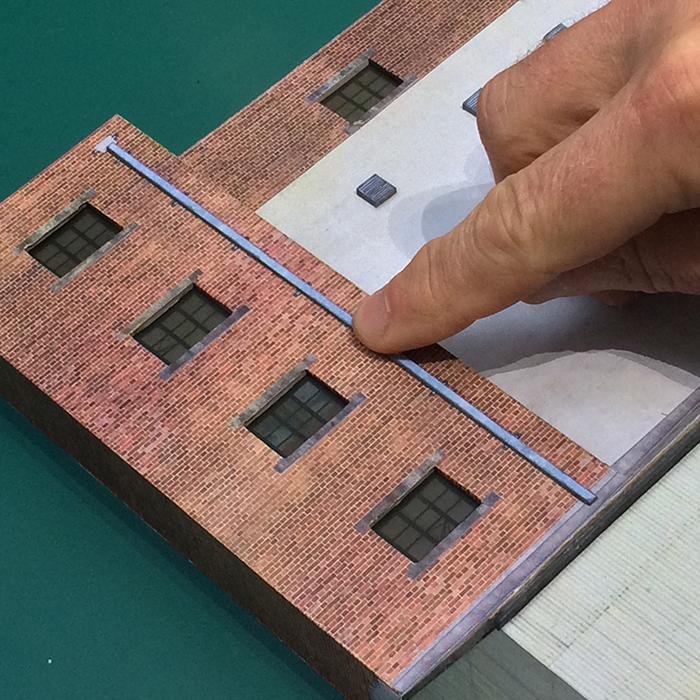
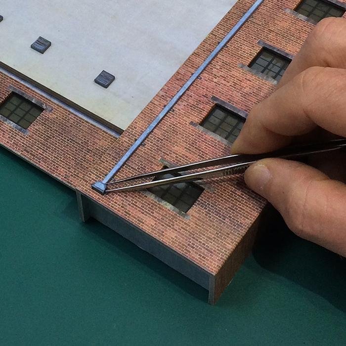
Squarely glue the longer of the two Downpipes into position along the joint.
17
Test fit and glue a Leader head squarely into position above the downpipe.
18
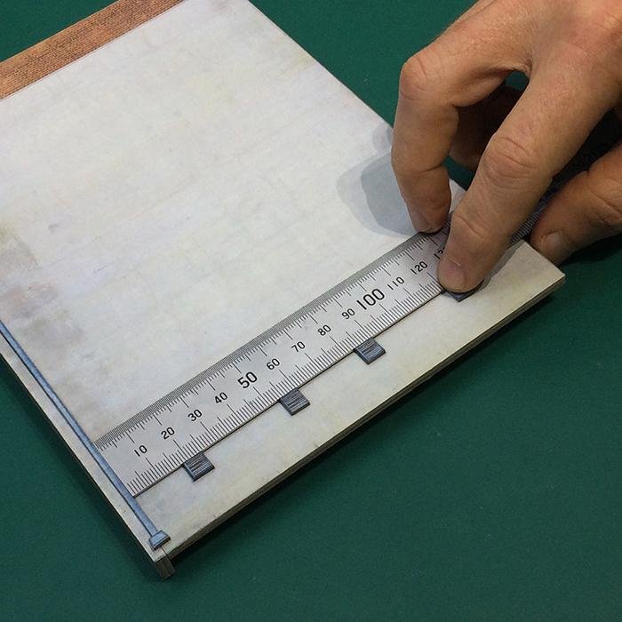
Use a straight edge to squarely glue the four Silo vents into position.
19
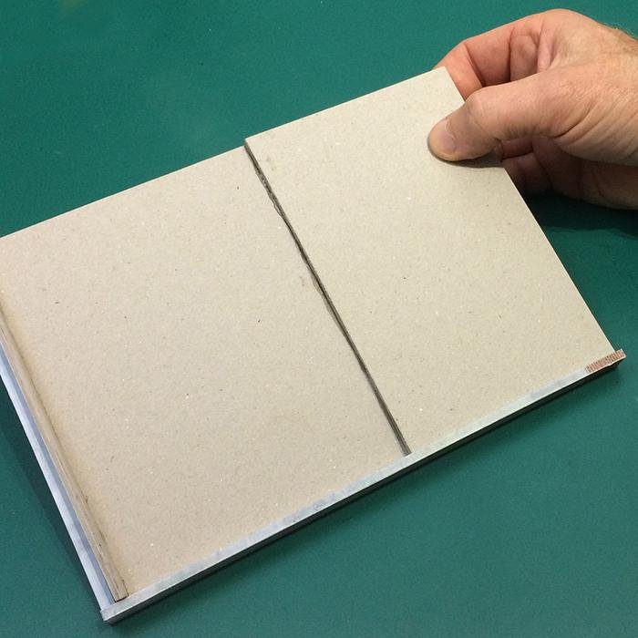
Neatly cut two sections of scrap card and glue them back of the Silo front wall for reinforcement. Apply weight or clamp to ensure good adhesion.
20
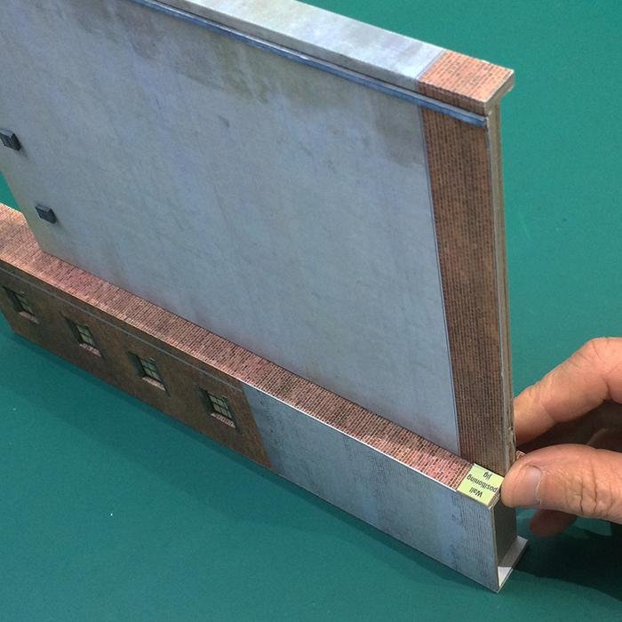
Using the small yellow Wall positioning jig, test fit and glue the Silo squarely into position on to your chosen side of the Elevator.
21
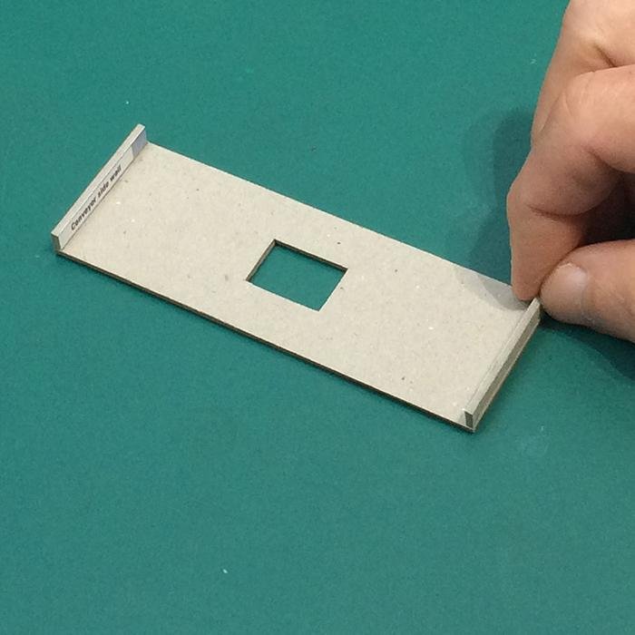
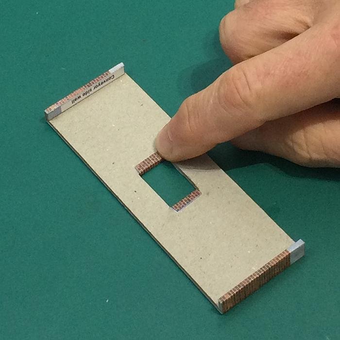
Squarely glue the two Conveyor side walls into position over the Conveyor front wall base layer.
22
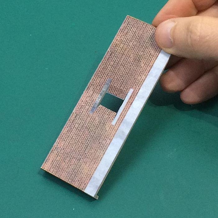
Carefully wrap and glue the Conveyor front wall cover layer over the Conveyor base layer structure. Check for bubbles and creases.
23
Flip the wall over (print down) and apply a thin bead of glue along the window flaps and gently fold them tightly around the opening.
24
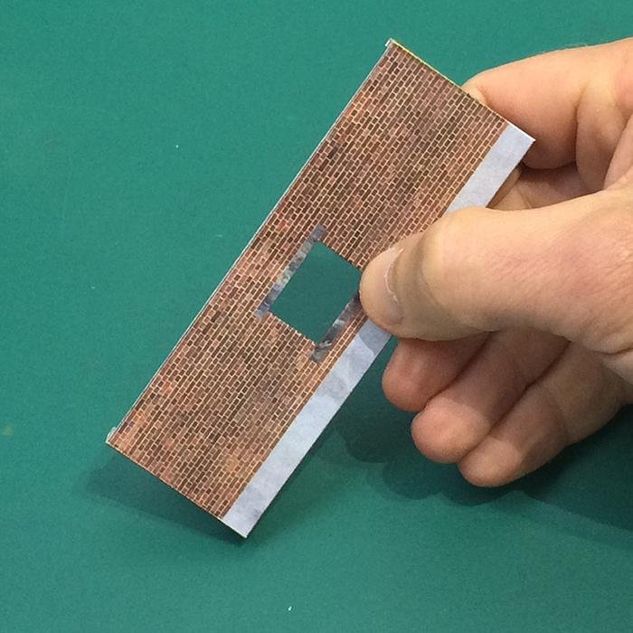
Glue the Conveyor sill into position using the cover layer from the print sheet.
25
Apply a thin bead of glue around the window opening and squarely position the Window.Turn the wall over and check that the window is sitting squarely within the opening.
26
Test fit and glue the Conveyor roof squarely into position.
27
Sitting the structure on a level surface, squarely glue the Conveyor into position.
28
Lay the Loader side wall print side down and glue Loader side walls (internal) into position.
29
Carefully fold the overhanging flaps tightly around the doorway edges.
30
Placing the Loader wall (internal) on a level surface, squarely glue the Loader columns into position.
31
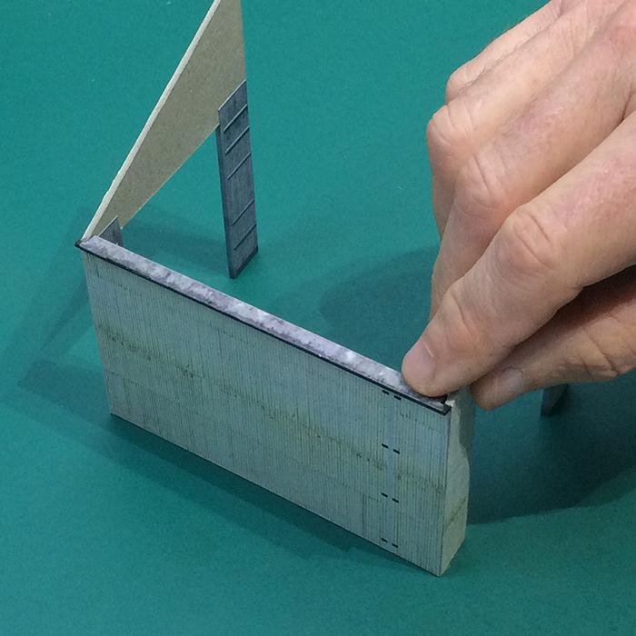
Test fit and glue the Loader side wall squarely into position. Use a small square or block to check that all the walls are perpendicular.
32
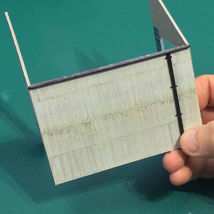
Squarely glue the Loader wall (external) into position. Check for bubbles and creases.
33
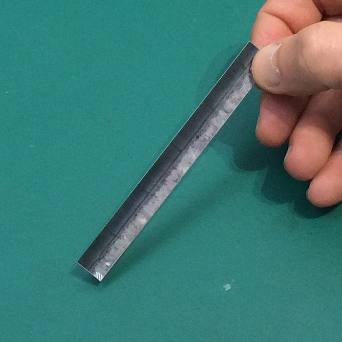
Fold along the blue dotted lines and cut out the Loader gutter cover layer. Using the fold as a guide carefully glue the Loader gutter base layer along the side with the grey hatched areas.
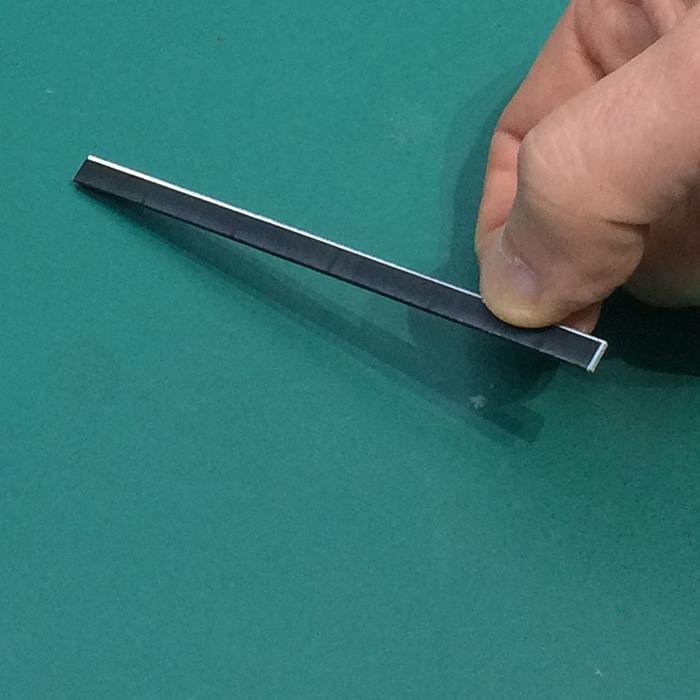
34
Wrap and glue the remaining flap around the base layer.
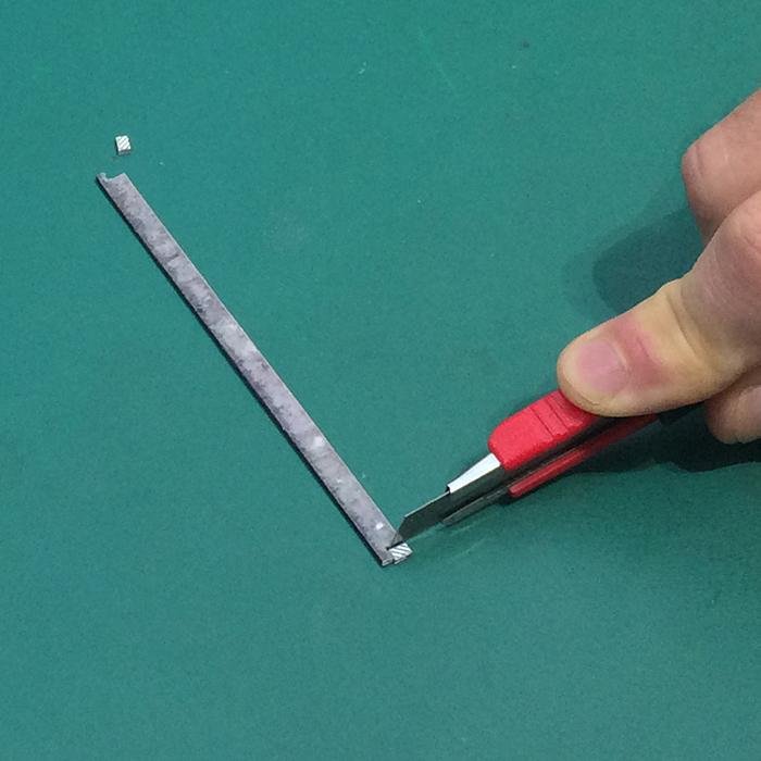
35
Once the glue has set, use a fresh blade to carefully cut away the grey hatched sections at each end.
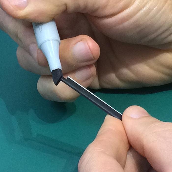
36
Carefully dab the ends with a black marker pen.
37
Test fit and glue the Gutter squarely into position.
38
Squarely glue the Loader downpipe into position.
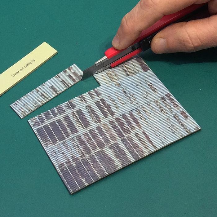
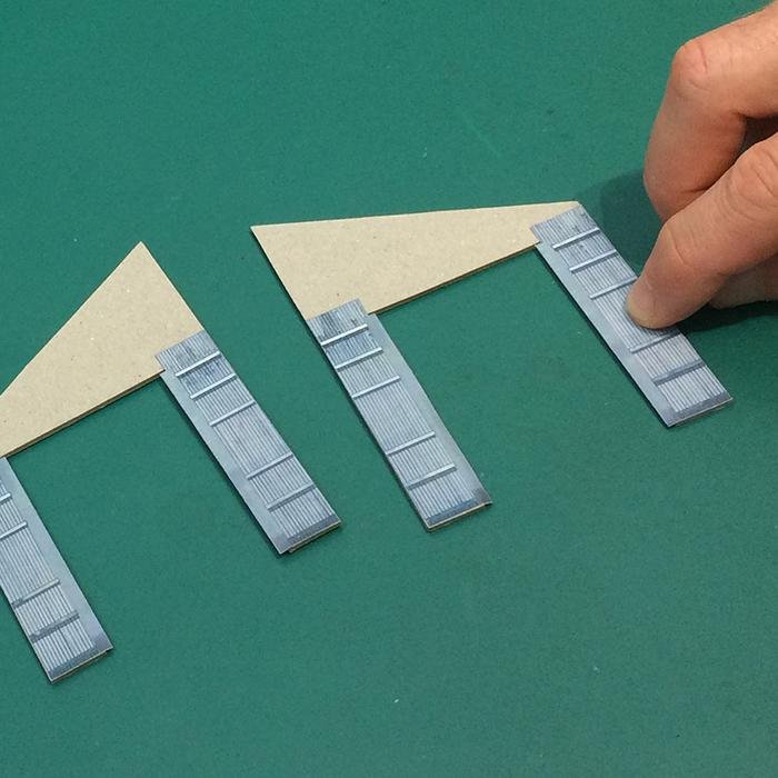
39
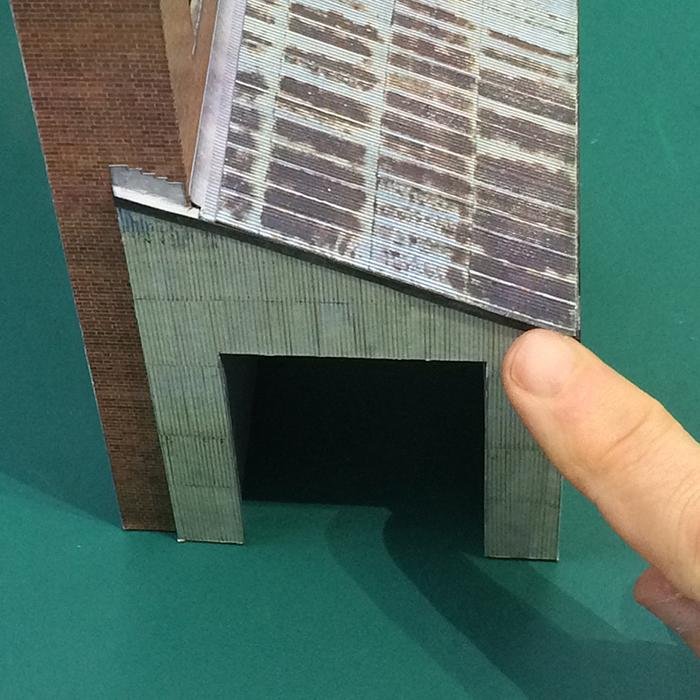
Depending on which side you have positioned the silo, cutaway the upper top corner using the Loader roof cutting jig.
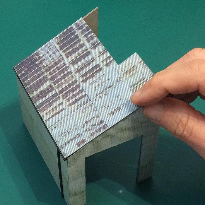
40
Squarely glue the Loader roof into position.
41
Sitting the structure on a level surface, test fit and glue the Loader squarely into position.
42
Gently fold the Loader roof flashing A and B down their centres and glue them squarely into position.
43
Test fit and glue the two Loader roof flashing C sections into position.
44
Squarely glue the remaining shorter Downpipe into position.
45
Test fit and glue the remaining Leader head squarely into position above the downpipe.
46
Carefully glue the two Bargeboards into position.
47
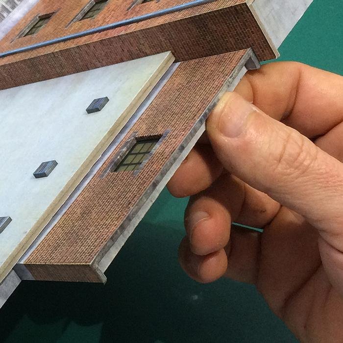
Test fit and glue the Elevator coping squarely into position.
48
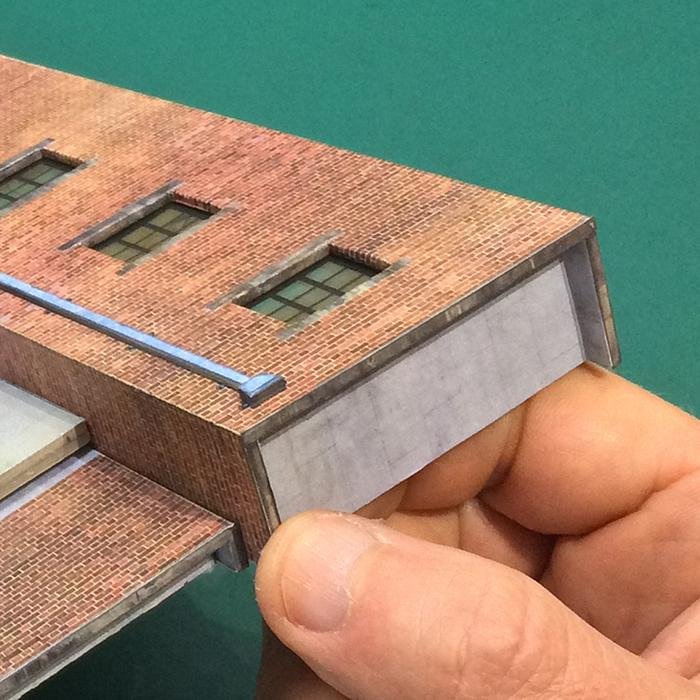
Test fit and glue the Conveyor coping squarely into position.
49
Test fit and glue the Silo coping squarely into position.